Dawlance AC Error
Codes


2 . Troubleshooting for Typical Faults
Troubleshooting sequence: Firstly, view the error description according to the error code on the
display. If E5 is displayed, it is needed to open the electric box of outdoor unit and record the LED
indication on the outdoor main control board. Then, find out the fault by referring to the LED
Indication Codes of Outdoor Main Control Board. After confirming the fault, find the cause
according to the instructions below:
A. Communication Fault (E6)
Check the communication wire between indoor unit and outdoor unit to ensure if the wire is
open circuited or short circuited and if the connector is loose.
B. Temperature Sensor Fault (F0, F1, F2, F3, F4 and F5)
Check if the wire from temperature sensor to mainboard is loose. Insert tightly if loose. If the
temperature sensor does not loosen from the mainboard, pull off the temperature sensor and
use multimeter to measure the resistance on the two ends of temperature sensor. If the
resistance is infinite high or very low (close to “0”), we can judge that the sensor is damaged
and shall be replaced. For the position of each temperature sensor on mainboard, please see
the PBC interface diagram attached.
C. High Pressure Protection
When high pressure protection is detected for 3 seconds successively, the unit will shut down
all the loads (except the 4-way valve of heating) and shield all the keys and remote signals
except the On/Off, in which case the run indicator will blink (or display fault code E1) and the
buzzer will alarm. The fault cannot be restored automatically. You shall need to press ON/Off
to stop the unit, then turn off the indicator (or clear E1 display) before pressing ON/OFF. The
unit will be restarted if the high pressure protection disappears. Otherwise, the run indicator
will blink (or display fault code E1) and the buzzer will alarm.
D. Low Pressure Protection
It will be deemed low-pressure protection as long as it is detected for 30 seconds
successively that the low-pressure switch is cut off, in which case the indicator will blink (or
display E3), all the loads will be stopped (except the 4-way valve of heating). If the fault is
eliminated, the compressor will be restarted after 3 minutes. If three low-pressure faults of
compressor are detected successively in 30 minutes from the first detection to the occurrence
of fault, the indicator will blink (or display E3) and the buzzer will alarm. The unit cannot be
restored automatically. You shall need to pre ss ON/Off to stop the unit, then turn off the
indicator before pressing ON/OFF. The unit will be restarted if the high pressure protection
disappears. Otherwise, the run indicator will blink (or display fault code E3) and the buzzer
will alarm.
E. Exhaust Over temperature Protection
After the compressor is started, it is detected for 30 seconds successively that the exhaust
temperature is higher than 115¥ ; E4 is displayed; and all the loads will be stopped (except
the 4-way valve of heating). After the compressor is stopped for 3 minutes, the fault code will
be cleared and the complete unit will resume to operation if the exhaust temperature is lower
than 90¥ . If such protection occurs three time successively within 30 minutes, the complete
unit cannot resume to operation, in which case E4 will be displayed and the buzzer will alarm.
You shall need to press ON/Off to stop the unit and then press ON/OFF again. If the exhaust
temperature is lower than 90¥ , the unit will run under preset mode.
F. Communication Fault between Main Controller and Inverter
Check if the communication wire between main control board and inverter is loose or broken.
G. E5 Protection (Overcurrent Protection or Inverter Fault)
Firstly, please check if the overload switch of the compressor is open. If it is not open or the
compressor has no overload switch, please refer to the troubleshooting process for inverter.
3. Inverter Troubleshooting
3.1 Typical Troubleshooting for Inverter GUHD09NK3AO, GUHD12NK3AO and GUHD18NK3AO
3.1.1 Troubleshooting and Treatment of Inverter Faults
(1) DC Overvoltage: If it is detected that the DV voltage is higher than 420V upon energization,
this fault will be alarmed. It is non-restorable if this protection occurs six times successively in
1 hour. In this case, you must de-energize, discharge completely and re-energize before you
can eliminate this fault.
(2) DC Undervoltage: If it is detected that the DV voltage is lower than 200V upon energization,
this fault will be alarmed. It is non-restorable if this protection occurs six times successively in
1 hour. In this case, you must de-energize, discharge completely and re-energize before you
can eliminate this fault.
(3) Inverter Module Resetting: Initialize the inverter program. This fault is alarmed upon
energization after each de-energization or upon resetting of inverter chip caused by some
interference. 5s will be displayed after occurrence of this fault. Note: It is normal that this
alarm will occur upon energization after de-energization.
(4) Inverter IPM Abnormal: This fault is alarmed when it is detected that IMP module or PFC
module is abnormal. It is non-restorable if this protection occurs six times successively in 1
hour. In this case, you must de-energize, discharge completely and re-energize before you
can eliminate this fault.
(5) Radiator Fin Overheat Protection: This fault is alarmed when it is detected in 1s successively
that the radiator fin temperature is higher than 105¥ . It is non-restorable if this protection
occurs six times successively in 1 hour. In this case, you must de-energize, discharge
completely and re-energize before you can eliminate this fault.
(6) Compressor Overcurrent Protection: This fault is alarmed when it is detected in 1ms
successively that the transient current of compressor is higher than 18A. It is non-restorable if
this protection occurs six times successively in 1 hour. In this case, you must de-energize,
discharge completely and re-energize before you can eliminate this fault.
(7) Compressor in Loss of Synchronization: This fault is alarmed when it is detected in 2s
successively that the negative potential of the compressor in run period is lower than 20V. It is
non-restorable if this protection occurs six times successively in 1 hour. In this case, you must
de-energize, discharge completely and re-energize before you can eliminate this fault.
(8) Compressor Over-frequency Protection: This fault is alarmed when it is detected in 2s
successively that the working frequency of compressor is higher than 200HZ or the difference
between working frequency and preset frequency is over 40Hz. It is non-restorable if this
protection occurs six times successively in 1 hour. In this case, you must de-energize,
discharge completely and re-energize before you can eliminate this fault.
(9) Communication Fault between Inverter and Main Controller: This fault is alarmed when it is
detected in 60s successively that it cannot communicate with the main controller normally.
This fault can be restored automatically.
(10) Current Detection Circuit Fault: This fault is alarmed when it is detected that the average bias
voltage is higher than 12.5% of 1.65V. It is non-restorable if this protection occurs six times
successively in 1 hour. In this case, you must de-energize, discharge completely and
re-energize before you can eliminate this fault.
3.1.2 Troubleshooting for Typical Inverter Faults
3.1.2.1 Switch Power Module is damaged.
The reasons that might cause damage to switch power module include:
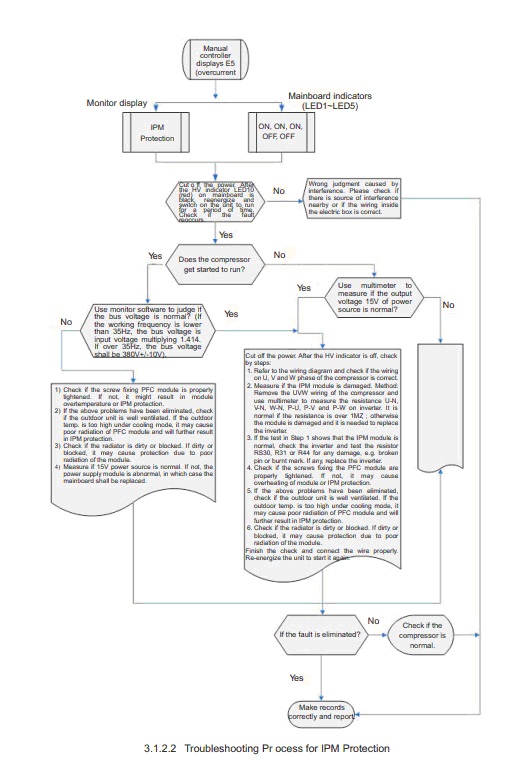
 3.1.2.2 IPM Module Protection
The possible reasons causing inverter IPM protection include:
z The screws fixing the IPM module or PFC module is not properly tightened.
z The IPM module or PFC module is damaged.
z The IPM module or PFC module is in poor radiation.
z The compressor is abnormal or the compressor wiring is wrong.
z The current test resistor R30, R31 or R44 is damaged.
z Interference.
Error Code
|
Malfunction
|
E0
|
Water pump malfunction
|
E1
|
High pressure protection of compressor
|
E2
|
Indoor anti-frozen protection
|
E3
|
Low pressure protection of compressor
|
E4
|
Air discharge high-temperature protection of compressor
|
E5
|
Overload protection of compressor or Inverter error
|
E6
|
Communication malfunction
|
E8
|
Indoor fan protection
|
E9
|
Water flow protection
|
F0
|
Malfunction of indoor environment sensor at air return
vent
|
F1
|
Evaporator sensor malfunction
|
F2
|
Condenser sensor malfunction
|
F3
|
Outdoor environment sensor malfunction
|
F4
|
Malfunction of air discharge sensor
|
F5
|
Malfunction of environment sensor on displayer
|
EH
|
Auxiliary electric heater malfunction
|
Troubleshooting sequence: Firstly, view the error description according to the error code on the
display. If E5 is displayed, it is needed to open the electric box of outdoor unit and record the LED
indication on the outdoor main control board. Then, find out the fault by referring to the LED
Indication Codes of Outdoor Main Control Board. After confirming the fault, find the cause
according to the instructions below:
A. Communication Fault (E6)
Check the communication wire between indoor unit and outdoor unit to ensure if the wire is
open circuited or short circuited and if the connector is loose.
B. Temperature Sensor Fault (F0, F1, F2, F3, F4 and F5)
Check if the wire from temperature sensor to mainboard is loose. Insert tightly if loose. If the
temperature sensor does not loosen from the mainboard, pull off the temperature sensor and
use multimeter to measure the resistance on the two ends of temperature sensor. If the
resistance is infinite high or very low (close to “0”), we can judge that the sensor is damaged
and shall be replaced. For the position of each temperature sensor on mainboard, please see
the PBC interface diagram attached.
C. High Pressure Protection
When high pressure protection is detected for 3 seconds successively, the unit will shut down
all the loads (except the 4-way valve of heating) and shield all the keys and remote signals
except the On/Off, in which case the run indicator will blink (or display fault code E1) and the
buzzer will alarm. The fault cannot be restored automatically. You shall need to press ON/Off
to stop the unit, then turn off the indicator (or clear E1 display) before pressing ON/OFF. The
unit will be restarted if the high pressure protection disappears. Otherwise, the run indicator
will blink (or display fault code E1) and the buzzer will alarm.
D. Low Pressure Protection
It will be deemed low-pressure protection as long as it is detected for 30 seconds
successively that the low-pressure switch is cut off, in which case the indicator will blink (or
display E3), all the loads will be stopped (except the 4-way valve of heating). If the fault is
eliminated, the compressor will be restarted after 3 minutes. If three low-pressure faults of
compressor are detected successively in 30 minutes from the first detection to the occurrence
of fault, the indicator will blink (or display E3) and the buzzer will alarm. The unit cannot be
restored automatically. You shall need to pre ss ON/Off to stop the unit, then turn off the
indicator before pressing ON/OFF. The unit will be restarted if the high pressure protection
disappears. Otherwise, the run indicator will blink (or display fault code E3) and the buzzer
will alarm.
E. Exhaust Over temperature Protection
After the compressor is started, it is detected for 30 seconds successively that the exhaust
temperature is higher than 115¥ ; E4 is displayed; and all the loads will be stopped (except
the 4-way valve of heating). After the compressor is stopped for 3 minutes, the fault code will
be cleared and the complete unit will resume to operation if the exhaust temperature is lower
than 90¥ . If such protection occurs three time successively within 30 minutes, the complete
unit cannot resume to operation, in which case E4 will be displayed and the buzzer will alarm.
You shall need to press ON/Off to stop the unit and then press ON/OFF again. If the exhaust
temperature is lower than 90¥ , the unit will run under preset mode.
F. Communication Fault between Main Controller and Inverter
Check if the communication wire between main control board and inverter is loose or broken.
G. E5 Protection (Overcurrent Protection or Inverter Fault)
Firstly, please check if the overload switch of the compressor is open. If it is not open or the
compressor has no overload switch, please refer to the troubleshooting process for inverter.
3. Inverter Troubleshooting
3.1 Typical Troubleshooting for Inverter GUHD09NK3AO, GUHD12NK3AO and GUHD18NK3AO
3.1.1 Troubleshooting and Treatment of Inverter Faults
(1) DC Overvoltage: If it is detected that the DV voltage is higher than 420V upon energization,
this fault will be alarmed. It is non-restorable if this protection occurs six times successively in
1 hour. In this case, you must de-energize, discharge completely and re-energize before you
can eliminate this fault.
(2) DC Undervoltage: If it is detected that the DV voltage is lower than 200V upon energization,
this fault will be alarmed. It is non-restorable if this protection occurs six times successively in
1 hour. In this case, you must de-energize, discharge completely and re-energize before you
can eliminate this fault.
(3) Inverter Module Resetting: Initialize the inverter program. This fault is alarmed upon
energization after each de-energization or upon resetting of inverter chip caused by some
interference. 5s will be displayed after occurrence of this fault. Note: It is normal that this
alarm will occur upon energization after de-energization.
(4) Inverter IPM Abnormal: This fault is alarmed when it is detected that IMP module or PFC
module is abnormal. It is non-restorable if this protection occurs six times successively in 1
hour. In this case, you must de-energize, discharge completely and re-energize before you
can eliminate this fault.
(5) Radiator Fin Overheat Protection: This fault is alarmed when it is detected in 1s successively
that the radiator fin temperature is higher than 105¥ . It is non-restorable if this protection
occurs six times successively in 1 hour. In this case, you must de-energize, discharge
completely and re-energize before you can eliminate this fault.
(6) Compressor Overcurrent Protection: This fault is alarmed when it is detected in 1ms
successively that the transient current of compressor is higher than 18A. It is non-restorable if
this protection occurs six times successively in 1 hour. In this case, you must de-energize,
discharge completely and re-energize before you can eliminate this fault.
(7) Compressor in Loss of Synchronization: This fault is alarmed when it is detected in 2s
successively that the negative potential of the compressor in run period is lower than 20V. It is
non-restorable if this protection occurs six times successively in 1 hour. In this case, you must
de-energize, discharge completely and re-energize before you can eliminate this fault.
(8) Compressor Over-frequency Protection: This fault is alarmed when it is detected in 2s
successively that the working frequency of compressor is higher than 200HZ or the difference
between working frequency and preset frequency is over 40Hz. It is non-restorable if this
protection occurs six times successively in 1 hour. In this case, you must de-energize,
discharge completely and re-energize before you can eliminate this fault.
(9) Communication Fault between Inverter and Main Controller: This fault is alarmed when it is
detected in 60s successively that it cannot communicate with the main controller normally.
This fault can be restored automatically.
(10) Current Detection Circuit Fault: This fault is alarmed when it is detected that the average bias
voltage is higher than 12.5% of 1.65V. It is non-restorable if this protection occurs six times
successively in 1 hour. In this case, you must de-energize, discharge completely and
re-energize before you can eliminate this fault.
3.1.2 Troubleshooting for Typical Inverter Faults
3.1.2.1 Switch Power Module is damaged.
The reasons that might cause damage to switch power module include:
- High-frequency transformer is damaged.
- The IC card for switch power control is damaged.
- The loads short circuit the 12V indicator.
The possible reasons causing inverter IPM protection include:
z The screws fixing the IPM module or PFC module is not properly tightened.
z The IPM module or PFC module is damaged.
z The IPM module or PFC module is in poor radiation.
z The compressor is abnormal or the compressor wiring is wrong.
z The current test resistor R30, R31 or R44 is damaged.
z Interference.
